Dogbone pattern generation under unequal anisotropy
See code in GitLab.
Author: Karli Gillette karli.gillette@gmail.com
Introduction
Unequal anisotropy ratios, as seen in cardiac tissue, can be responsible for the formation of unexpectedly complex polarization patterns when applying stimuli through point sources. While an elliptical polarization pattern is normally expected when applying a strong source potential, a dogbone pattern can be achieved under unequal conductive anisotropy. The dogbone pattern is termed for the occurrence of two circular regions of opposite polarity (virtual electrodes) that arise. The pattern can be achieved by applying anodal (-) or cathodal(+) simulation. To run the experiments of this example change directories as follows:
cd ${EXAMPLES}/02_EP_tissue/16_bidm_dogboneExperimental setup
The geometry and the electrodes are defined as follows:
Model: A hexahedral FE model with dimensions 20.0mm x 20.0mm x 10.0mm is submersed in a bath on both the upper and lower ends with thickness 5.0 mm. Fibers are assigned in the model ranging from -60 to 60 degrees. The model is automatically generated in mesher during the simulation.
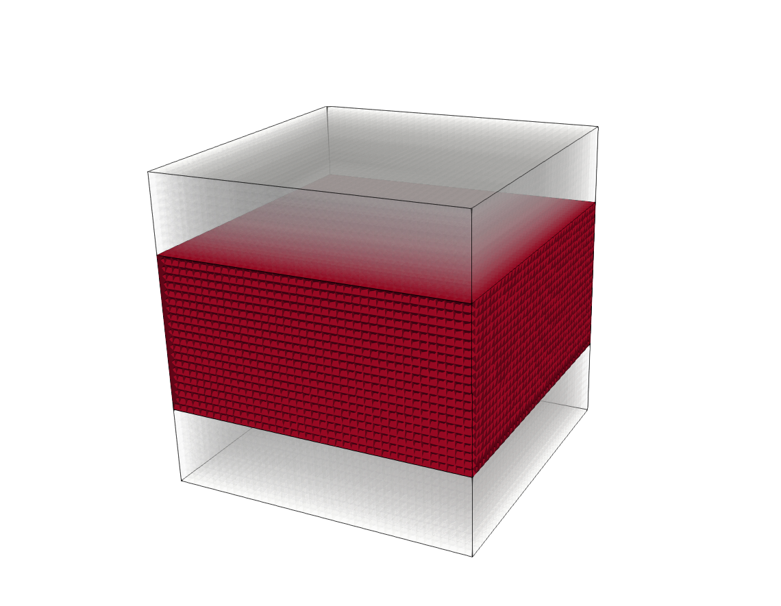
Stimulus: A strong anodal or cathodal extracellular point stimulus (pt_stim) is applied just above the top surface of the mesh in the bath. An extracellular ground electrode (GND) is assigned to the bottom of the bath.
Assigning unequal anisotropy: Conductivities are applied either anisotropically using the default openCARP values to generate a dogbone pattern:
gregion[0].g_il          = 0.174
gregion[0].g_it          = 0.019
gregion[0].g_in          = 0.019
gregion[0].g_el          = 0.625
gregion[0].g_et          = 0.236
gregion[0].g_en          = 0.236
or to a single conductivity values of 0.625 to generate an elliptic pattern.
Usage
The following optional arguments are available (default values are indicated):
./run.py --visualize         # visualize results with meshalyzer
         --pt_stim           = anode (default), cathode #type of applied point source stimulus
         --no_anisotropy     # turn off conductive anisotropy
         --res               # changes the resolution of the mesh [0.25,0.75] with default 0.5.
If the program is run with the --visualize option, meshalyzer will automatically
load the model with applied activation data showing the occurrence of the dog bone (8 seconds) in
the presence of anisotropy or an elliptical pattern.
Note
This mesh has a fairly high resolution and may take longer to run. Try increasing the number of cores using the
''--np'' option or changing the resolution of the mesh with the --res option.
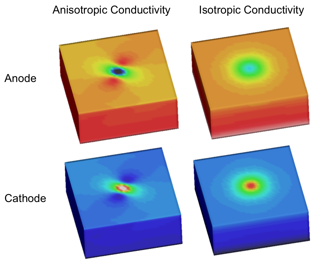
Expected results
The expected outcomes of the four cases of applying a cathode or anode point stimulus with or without anisotropy are shown:
Recent questions tagged experiments, examples, tissue
There are tagged with experiments, examples, tissue.
Here we display the 5 most recent questions. You can click on each tag to show all questions for this tag.
You can also ask a new question.