Region tagging
See code in GitLab.
Author: Edward Vigmond edward.vigmond@u-bordeaux.fr
In openCARP regions are used to manage the assignment of heterogeneous tissue properties. This example explains the different approches of how regions can be defined. To run the experiments of this example do
cd ${EXAMPLES}/02_EP_tissue/04_taggingRegions
Regions are a general concept in openCARP for volumes which share common properties, be they ionic, mechanical or
in terms of conductivity. For a general introduction of this concept see the region section of the manual.
In the mesh files, elements may be given a region tag as an optional field in the .elem file.
A region tag is simply an integer associated with an element. openCARP regions are then conglomerations of element region tags. The following is an example of how to assign some region tags to IMP and conductivity regions:
imp_region[1].num_IDs = 2
imp_region[1].ID[0] = 1000
imp_region[1].ID[1] = 1100

gregion[3].num_IDs = 5
gregion[3].ID = 100 200 201 1000 2000
Two slightly different syntaxes are shown for specifying the region tags.
Note
If a region tag is not explicitly included in any region, it will be assigned to region 0.
Dynamic retagging
Each element in a mesh is designated as being in a region, and properties, be they electrical or mechanical, are assigned based on region. It may be desired to change properties in a small volume which is not defined in the original mesh. To avoid touching the mesh files, dynamic tagging was introduced.
Essentially, a geometrical volume is defined, and all elements wthin the volume are given a new tag. Overlaps are governed by a simple rule: the highest region tag wins. This also implies that your reassigned tags have to be higher than the original model tags. The case where some but not all of an element's nodes are contained with the tagging volume must be handled. By default, elements with at least one node in the tagging volume are included, but ensuring that only elements with all nodes contained can be enabled by setting an option below.(no_split_elem)
Tag volumes can also be created by simply specifying a list of elements within the volume.
Region definitions
The number of new tag regions is specified by numtagreg.
For each region defined by tagreg[*], the table below lists the available fields to set. Bolded fields need to be specified
and depending on the value of type, different fields define the geometrical volume. Note that the units are micrometers.
See the figure below:
| Field | Meaning |
|---|---|
| tag | numerical value of tag region |
| name | string to identify retagged region |
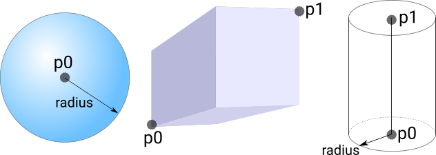
| type | how to define region (1=sphere,2=block,3=cylinder,4=elemfile) |
| no_elem_split | all nodes of an element must be contained |
| p0 | first point to define volume. type=1|2|3 |
| p1 | second point to define volume. type=2|3 |
| radius | radius for spherical/cylindrical volumes. type=1|3 |
elemfile |
file with elements contained in tag region. type=4 The
file needs the extension |
The tagging volumes are defined according to the following diagram:
Mesher tagging
When using the mesher program, tag volumes can be assigned to the blocks of tissue but the rules are slightly different.
Note
With mesher, bounds are defined in units of cm, not micrometers and the cylinder definition is different.
For each tag volume defined by regdef[*], the table below lists the available fields to set. Bolded fields need to be specified
and depending on the value of type, different fields define the geometrical volume.
| Field | Meaning |
|---|---|
| tag | numerical value of the tag |
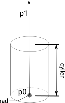
| type | how to define tag volume (0=block,1=sphere,2=cylinder) |
| p0 | first point to define volume. type=0|1|2 |
| p1 | UR point for block (type=0), or axis for cylinder which will be normalized (type=2) |
| rad | radius for spherical/cylindrical volumes. type=1|2 |
| cyllen | cylinder length for cylindrical volumes. type=2 |
| bath | set true for a bath region |
If an element was originally created as bath, it cannot be turned into myocardium but myocardium can be turned into bath.
To deal with overlapping regions, the rules are also different from dynamic tagging.
For mesher, an element belongs to the first region which contains it.
Thus, the order of region definitions is important. An option is also available -first_reg,
which if set false, scans the region definitions and assigns the last region which contains an element.
Example
The following options are the pertinent ones for running the example
run.py -h
    --mesher [{sphere,block,steps} [{sphere,block,steps} ...]]
                    regions implemented in mesher
    --dynamic [{cylinder,sphere,block} [{cylinder,sphere,block} ...]]
                    regions implemented dynamically
    --add-bath            mesher regions are bath
Multiple regions can be created in mesher or dynamically afterwards. Start with a single region implemented in mesher
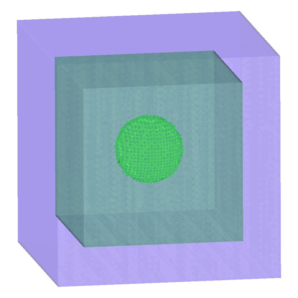
./run.py --mesher sphere --visualizeTo see the regions better, click Image/Randomly color/surfaces from the menu bar at the top.
The colors are random, so if you do not like them, randomly color again (and again ...). You should see 3 regions: the bath, the original block of tissue, and the spherical region.
To see the points in the region,
- turn off clipping (open the clipping window under
Data/Clipping) - In the
Regionsection in the control window, check only the region 10 - Check the
Verticesandvisiblebuttons - To control the size of the points, click on
propsbeside the Vertices button. - Reduce the opacity of the surfaces (set it in
Fill colorof theSurfacestab)
It should now resemble the figure below.
Try adding another sphere, this time dynamically added afterwards at a different location
./run.py --mesher sphere --dynamic sphere --visualizeExperiment with adding different combinations of regions. The order of multiple regions specified with the --mesher and --dynamic options matters. With this script, the first contained region is used for dynamic retagging.
To see the points contained in the regions, display vertices as above, and click Image/Randomly color/surfaces
to colour them differently for each tag region.
For a more detailed introduction to the region concept as implemented in openCARP see the Region Tagging Section of the manual.
Recent questions tagged experiments, examples, tissue, region, mesher
There are tagged with experiments, examples, tissue, region, mesher.
Here we display the 5 most recent questions. You can click on each tag to show all questions for this tag.
You can also ask a new question.